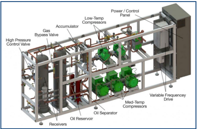
Simplified Labeled Diagram of an Advansor Booster System Compressor Rack
Advansor CO2 systems use many components that are common to other types of DX systems as well as some that are specifically designed for the application. Like any other DX type of system, the Advansor system relies on the four principle components which include compressors, evaporators, condensers and expansion valves.
.
1.C.III.a CO2 Compressors
As with
any other type of DX system, the CO2
booster system uses compressors to move the refrigerant in it.
Unlike
most other types of these systems, which are typically divided
between medium temperature and low temperature
applications, however, the Advansor system uses two sets of compressors
in the same system. The
low-temperature “subcritical” compressors operate well below the
critical point in much the same way CO2
compressors do in cascade systems. Like those compressors, the
ones on the Advansor CO2 system receive
suction gas from the low-temp evaporators. The suction gas enters
the compressors at 183 psig and the
discharge gas leaves them at 410 psig.
At the same time, the discharge from the low temperature compressors combines with gas from the medium-temp evaporators to become the suction gas for the medium-temp compressors. The Advansor system can use either scroll or semi-hermetic reciprocating compressors for the low-temp portion of the system. These compressors sit on the top of the rack. Only semi-hermetic reciprocating compressors can be used for medium-temperature portion of the system. These “transcritical” compressors sit on the bottom of the rack.
As medium-temp compressors, they discharge at anywhere from 560 to 1450 psig, depending on the ambient conditions. The action of the medium-temp compressors can be seen in the upper section (shaded upper area) of the chart around 385 psig when the gas enters the compressors. From there, again, depending on ambient conditions, the gas may reach to1385 psig as it discharges from the compressors and enters the condenser/gas cooler. Of course for the gasto reach that range, the ambient conditions must exceed 80°F.
Each
compressor is installed with some additional features including:
•
Bolted
to the frame on oil-resistant polymer mounts
•
Equipped
with service valves on the suction and discharge sides
•
Individual
oil switches and pressure switches are included on the discharge
side
•
Some
CO2 compressors contain relief valves to ambient (see the compressor
manufacturer’s operating specifications
for additional information)
• Crankcase
heaters to warm the oil whenever the compressors are not running
• Variable
frequency drives on the lead compressor for better capacity control
- Optional
with the lead low-temperature compressor
- Standard
on the lead medium-temperature compressor
1.C.III.b Oil Separator and Oil Requirements
The Advansor system uses the same oil management components system as those on conventional DX systems except that they are designed for the higher operating pressures needed for CO2. These include electronic oil level sensors, a separator, a reservoir, and a filter. Once the medium-temperature discharge gas leaves the medium-temp compressors, it passes through a highly efficient oil separator that uses coalescing filters to separate the oil from the refrigerant. The separator can be used with or without an external oil reservoir. Oil separators are a common component on DX systems of just about any type.
Only manufacturer-approved oil is permissible for use in the Advansor system. For very small systems (i.e., 2x2 models), the oil separator is equipped with an oil reservoir at the bottom of the unit from which the oil is fed back to the compressors according to demand. On booster rack models with external reservoirs, the oil separator is equipped with a larger filter. The oil from these units is fed from the oil separator to the reservoir through a solenoid valve that opens when the oil reaches a preset level in the separator. From there, the oil is fed from the reservoir to the compressors.
1.C.III.c Condenser/gas cooler
This component usually works the same way a condenser does in a conventional DX system. At ambient conditions below 80°F, medium-temperature discharge gas enters the condenser/gas cooler and rejects heat to the outside air as it passes through the coils of the unit. The main difference between it and a conventional condenser is that when the ambient temperature rises above 80°F, the system begins operating in the transcritical range. This means that the discharge gas passing through the system does not undergo any further state change but instead remains a supercritical gas, or fluid as it is otherwise known.
This last point is a key distinction. Under transcritical conditions, the discharge gas enters the condenser/gas cooler as a supercritical fluid and stays that way all the way through the condenser/gas cooler to the high pressure control valve. No condensing of the gas takes place as in a regular condenser. Below 80°F, however, the unit then works just like a condenser in a typical DX system. In the same way that efficiency gains are made on the compressors through the use of variable speed drives, so too are the fans on the condenser/gas cooler controlled. Also, the condenser/gas cooler is equipped with a shut-off valve for maintenance or other needs.
.
I.C.III.d High-Pressure Control Valve
Like the condenser/gas cooler, the high-pressure control valve works under two modes of operation. It usually controls subcooling in the condenser/gas cooler when that unit operates as a condenser. Under conditions during which the condenser/gas cooler is working as a gas cooler (above 80°F ambient), the valve controls pressure in it. The actuator in the valve can be accessed by removing three small bolts. The valve can then be operated manually with a hand magnet if necessary. Power to the valve is furnished from an uninterrupted power supply (UPS). The valve closes in case of a power failure.
I.C.III.e Flash Tank
The expanded gas from the high-pressure control valve flows into the flash tank. The flash tank is equipped with a flash gas bypass valve that maintains a set pressure in the tank. When opened, the valve bypasses excess vapor from the tank to the suction side of medium-temperature compressors.
I.C.IV OTHER SYSTEM COMPONENTS
I.C.IV.a Piping
One of the benefits of CO2 is its high volumetric capacity. This allows for smaller diameter piping to be used than would otherwise be needed for a HFC system of similar capacity. In fact, smaller diameters add to the overall advantages of the system since they decrease the refrigerant charge and handle higher pressures. Piping and elbows to and from the condenser/gas cooler should be carbon or stainless steel and should be installed to comply with appropriate standards. The piping is welded and must be coated with primer and varnish. During operation, the pipes can get hot (i.e., 250°F) and insulation is recommended anywhere they might be touched.